
A blog to help electrical engineers and students to learn electrical engineering topics. Basic Electrical Engineering, Power Systems, Electrical Machines, tec.. Now special course on MATLAB for Beginners.

Class

Class
Showing posts with label resistance. Show all posts

Monday, December 21, 2015

Resistance - Series and Parallel Connection


Series and parallel Connections

When several devices are connected end to end in such a way that there is only one path for the current to flow and so, the same current flows through each, then such a circuit is called a "series circuit". When several devices are connected to a common voltage in a certain manner that they provide alternative paths for the current.  Where the current in each path (device) will depend on its resistance.  Such a circuit is called “parallel circuit”.

Resistances in Series

When three resistors, R1, R2 and R3 are connected end to end as shown in the figure below, then it would be referred as resistances in series. In case of series connection, the equivalent resistance of the combination, is sum of these three electrical resistances.

Total voltage applied across the combination of resistances in series, is V. Let the current in the circuit is I. So this current I will pass through the resistance R1, R2 and R3. Applying Ohm’s law , it can be found that voltage drops across the resistances will be V1 = IR1, V2 = IR2 and V3 = IR3.
From figure, the total voltage is the sum of voltage drop across R1, R2 and R3, is V1, V2 and V3 respectively, 

            then     V   = V1 + V2 + V3
            \         V = IR1 + IR2 + IR3

            or         V = I (R1 + R2 + R3)

Now, if we consider the total combination of resistances as a single resistor of electric resistance value R, then according to Ohm’s law ,

                        V = IR

              \     IR = II (R1 + R2 + R3)

finally,            R = R1 + R2 + R3

So the above proof shows that equivalent resistance of a combination of resistances in series is equal to the sum of individual resistance. If there were n number of resistances instead of three resistances, the equivalent resistance will be
                       R = R1 + R2 + R3 + ………………..+Rn


Resistances in Parallel

Let’s three resistors of resistance value R1, R2 and R3 are connected in such a manner, that right side terminal of each resistor are connected together as shown in the figure below, and also left side terminal of each resistor are also connected together. This combination is called resistances in parallel.

If a voltage, V is applied across this combination, then it will draw a current I. As this current will get three parallel paths through these three electrical resistances, the electric current will be divided into three parts. Say currents I1, I1 and I1 pass through resistor R1, R2 and R3 respectively. The total source current will be sum f branch currents,

                   I = I1 + I2 + I3

Now, as from the figure it is clear that, each of the resistances in parallel, is connected across the same voltage source, the voltage drops across each resistor is same as source voltage V.

Hence,        I1 = V/R1I2 = V/R2 and I3 = V/R3,

and             I = V ⁄ R
where R is the equivalent resistance of the combination.
    \         V ⁄ R = V/RV/RV/R3
           
                   1 ⁄ R = 1/R1/R1/R3

The above expression represents equivalent resistance of resistor in parallel. If there were n number of resistances connected in parallel, instead of three resistances, the expression of equivalent resistance would be
                  1/R = 1/R1 + 1/R2 + 1/R3 + .......... + 1/Rn


Problem Solving

Example 1 : Three resistors of 5.8W, 10.7 W  and 6.5W are connected in series across a 127 V supply.  What is

a.     the total resistance of the circuit
b.     the total current in the circuit, and
c.   the voltage across each resistor?

Example 2 :  Find the effective resistance of 20 W,  30W  and 6W resistances connected in parallel.


Example 3 : In the circuit as shown in Figure R1 = 40 W, R2=120W, R3 = 80W. If the supply voltage V is equal to 220V then find out;


a.     The total resistance
b.     The total current
c.     The current in each resistance and
d.   Voltage across each resistance.


Wednesday, December 16, 2015

Ohm's Law


Ohm's law applies to electric conduction through conductors and may be stated as follows:-


‘The ratio of potential difference (V) between any two points on a conductor to the current (I) flowing between them, is constant, provided the temperature of the conductor does not change.’


In other words V/I = constant

or V /I = R

Where R is the resistance of the conductor between the two points considered


Put in another way, it simply means that provided R is kept constant, current is directly proportional to potential difference across the ends of the conductor. For a constant value of R, if the value of V is increased, the value of I increases; if V is decreased, then I decreases.  Also notice that if V is constant and R is increased, I decreases.  Similarly, if V is constant and R is decreased, I increases.


Figure show the current voltage relationship for R=10 ohm.

Material that obeys Ohm's Law is called 'ohmic' or 'linear'  because the potential difference across it varies linearly with the current. However this linear relationship between V and I does not apply to all non-metallic conductors.

Wednesday, December 9, 2015

What is Resistance


res symbol


Resistance:

Resistance may be defined as the property of a substance due to which it opposes (or restricts) the flow of electricity (or electrons) through it.

A resistor is a two-terminal electrical component that implements resistance in a electric  circuit. The resistance (R) of a resistor is defined as the ratio of voltage across it (V) to current through it (I)

rvi

The unit of Resistance:

The practical unit of resistance is ohm. A conductor is said to have a resistance of one ohm if it permits one ampere current to flow through it when on volt is impressed across its terminals. For insulators whose resistance are very high, a much bigger unit is used ie. mega ohm or kilo ohm. In the case of very small resistances, smaller units like milliohm or micro ohm are used. The symbol for ohm is Ω.

 Resistivity or Specific Resistance


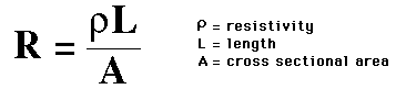
The electrical resistance of a wire would be expected to be greater for a longer wire, less for a wire of larger cross sectional area, and would be expected to depend upon the material out of which the wire is made. An object of uniform cross section has a resistance proportional to its resistivity and length and inversely proportional to its cross-sectional area

resistivity

The factor in the resistance which takes into account the nature of the material is the resistivity. Although it is temperature dependent, it can be used at a given temperature to calculate the resistance of a wire of given geometry. The inverse of resistivity is called conductivity. There are contexts where the use of conductivity is more convenient.

Temperature dependence


Resistance of wires, resistors, and other components change with temperature. Resistivity of metals typically increases as temperature is increased, while the resistivity of semiconductors typically decreases as temperature is increased.

Variation of resistance with temperature is given by:

tempres

where  \alpha is called the temperature coefficient of resistance


Based on resitance the substances may be classified as

  • Conductors

  • Semiconductors

  • Insulators

Conductors:

Some materials are willing to let a few electrons move from molecule to molecule. Materials that let electrons move through them are called "conductors". It is due to the presence of a large number of free or loosely attached electrons in their atoms. Although some are better than others, most metals are good conductors of electricity. Silver, Gold, and Platinum are very good conductors but are expensive, so they are not often used. Copper and Aluminum are reasonably good conductors and are fairly inexpensive. Thus the wiring in our houses is copper, and the high voltage electric lines that we see crossing the country use aluminum cables.

Insulators:

Other substances keep their electrons under very tight control. Materials that do not let electrons move through them are called "insulators". Glass is an example of a type of material that keeps its electrons tightly controlled. Glass is made of silicon molecules, organized very tightly in to crystaline structures. Glass is an extremely good insulator. Many plastics are good insulators too. Plastics are cheap, flexible, and durable


Conductance: - In verse of resistance, unit is Siemens (old unit mho)

Electrical conductivity = σ = 1/ρ