A blog to help electrical engineers and students to learn electrical engineering topics. Basic Electrical Engineering, Power Systems, Electrical Machines, tec.. Now special course on MATLAB for Beginners.

Class

Class
Showing posts with label DC machine. Show all posts

Thursday, December 24, 2015

Types of DC Generator and Their Characteristics


Types of DC Motor

D.C. generators are classified according to the method of their field excitation. These groupings are:
  1. Permanent magnet dc generators, where a permanent magnet is used to establish flux in the magnetic circuit.
  2. Separately-excited generators, where the field winding is connected to a source of supply other than the armature of its own machine.
  3. Self-excited generators, where the field winding receives its supply from the armature of its own machine, and which are sub-divided into
    1. Shunt
    2. Series, and
    3. Compound wound generators.
When the field winding of a d.c. machine is connected in parallel with the armature, as shown in Fig, the machine is said to be shunt wound. If the field winding is connected in series with the armature, then the machine is said to be series wound. A compound wound machine has a combination of series and shunt winding.

Characteristics

(a) Separately-excited generator


The two principal generator characteristics are the generated voltage/field current characteristics, called the open-circuit characteristic and the terminal voltage/load current characteristic, called the load characteristic. Typical separately-excited generator characteristics are shown in Figure.

When a load is connected across the armature terminals, a load current Ia will flow. The terminal voltage V will fall from its open-circuit e.m.f. E due to a volt drop caused by current flowing through the armature resistance, shown as Ra.
Terminal voltage,
E − IaRa

(b) Shunt wound generator

In a shunt wound generator the field winding is connected in parallel with the armature as shown in Figure. The field winding has a relatively high resistance and therefore the current carried is only a fraction of the armature current.
Terminal voltage, V = E - IaRa
Ia = If + I from Kirchhoff’s current law, where,
Ia = armature current,
If = field current = V/Rf
and I = load current

As the load current on a generator having constant field current and running at constant speed increases, the value of armature current increases, hence the armature volt drop, IaRa increases. The generated voltage E is larger than the terminal voltage V and the voltage equation for the armature circuit is V = E - IaRa. Since E is constant, V decreases with increasing load.


(c) Series-wound generator

In the series-wound generator the field winding is connected in series with the armature

Thus E is proportional to flux. For values of current below magnetic saturation, the flux is proportional to the current, hence E α I. For values of current above those required for magnetic saturation, the generated e.m.f. is approximately constant. The values of field resistance and armature resistance in a series wound machine are small; hence the terminal voltage V is very nearly equal to E.

In a series-wound generator, the field winding is in series with the armature and it is not possible to have a value of field current when the terminals are open circuited, thus it is not possible to obtain an open-circuit characteristic.

(d) Compound-wound generator

In the compound-wound generator two methods of connection are used, both having a mixture of shunt and series winding, designed to combine the advantages of each. Fig.(a) shows what is termed a long-shunt compound generator, and Fig.(b) shows a short-shunt compound generator. The latter is the most generally used form of D.C. generator.
 
In cumulative-compound machines the magnetic flux produced by the series and shunt fields are additive. Included in this group are over-compounded, level-compounded and under-compounded machines – the degree of compounding obtained depending on the number of turns of wire on the series winding.


Review Questions

1. With the increases in field excitation of a DC generator, its generated emf ________________
  1. decreases.
  2. increases.
  3. remains constant.
  4. increases up to a limit and then remains almost constant. 

2. Which of following DC generator will be in a position to build up without any residual magnetism in the field?
  1.  Compound. 
  2. Shunt.
  3. Series.
  4. None of them

3. Which of the following DC generators has rising V-I characteristics?
  1. Compound. 
  2. Shunt.
  3. Series.
  4. None of them.

4. The ___________________ generator has the poorest voltage regulation.
  1. under-compounded.
  2. differential compounded. 
  3. shunt. 
  4. over compounded.

5. The voltmeter connected across a generator reads voltage same at no load and at full load (rated). The generator is of the type
  1. level compound.
  2. series generator.
  3. short - shunt generator.
  4. shunt generator.


Friday, December 18, 2015

DC Generator Operating Principle - e.m.f. Equation


The basic principle of a DC machine is Faraday's laws of electromagnetic induction. According to these law, when an conductor moves in a magnetic field it cuts magnetic lines force, due to which an emf is induced in the conductor. The magnitude of this induced emf depends upon the rate of change of flux (magnetic line force) linkage with the conductor.When the armature rotates, the armature conductors cut the flux produced by the field windings (poles). Hence an emf is induced in the armature winding. The direction of induced current is given by Fleming’s right hand rule.
  
Let          Φ – Flux per pole in Wb
               Z – total number of conductors on the armature
               P – number of poles
               A – number of parallel paths on the armature
                           ( = P for Lap and = 2 for Wave)
               N – Speed of rotation of armature in rpm
               E – average emf induced
Then, total flux cut by a conductor taking one complete revolution,
d Φ = P Φ
Time taken for one complete revolution,
                        dt = 60/N seconds
According to faradays law of electromagnetic induction,
Emf induced per conductor,
                 

If there is Z number of conductors connected in A number of parallel paths,
                volts
Since, A, P, Z are constants,
                        E α N Φ

Monday, December 7, 2015

DC Machines - Introduction


dcmotor

Direct Current machines are energy transfer devices.
These machines can function as either a motor or a generator

Two related physical principles underlie the operation of generators and motors. The first is the principle of electromagnetic induction discovered by the British scientist Michael Faraday in 1831. If a conductor is moved through a magnetic field, or if the strength of a stationary conducting loop is made to vary, a current is set up or induced in the conductor. The converse of this principle is that of electromagnetic reaction, first observed by the French physicist André Marie Ampere in 1820. If a current is passed through a conductor located in a magnetic field, the field exerts a mechanical force on it.

Construction


DC motors and generators have the same basic construction, differing primarily in the energy conversion.

The basic requirements are a conductor, flux and relative motion between them. The physical structure of the machine consists of 2 parts: the stator and the rotor. The stationary part consists of the frame, and the pole pieces, which project inward and provide a path for the magnetic flux.

dcmachine1

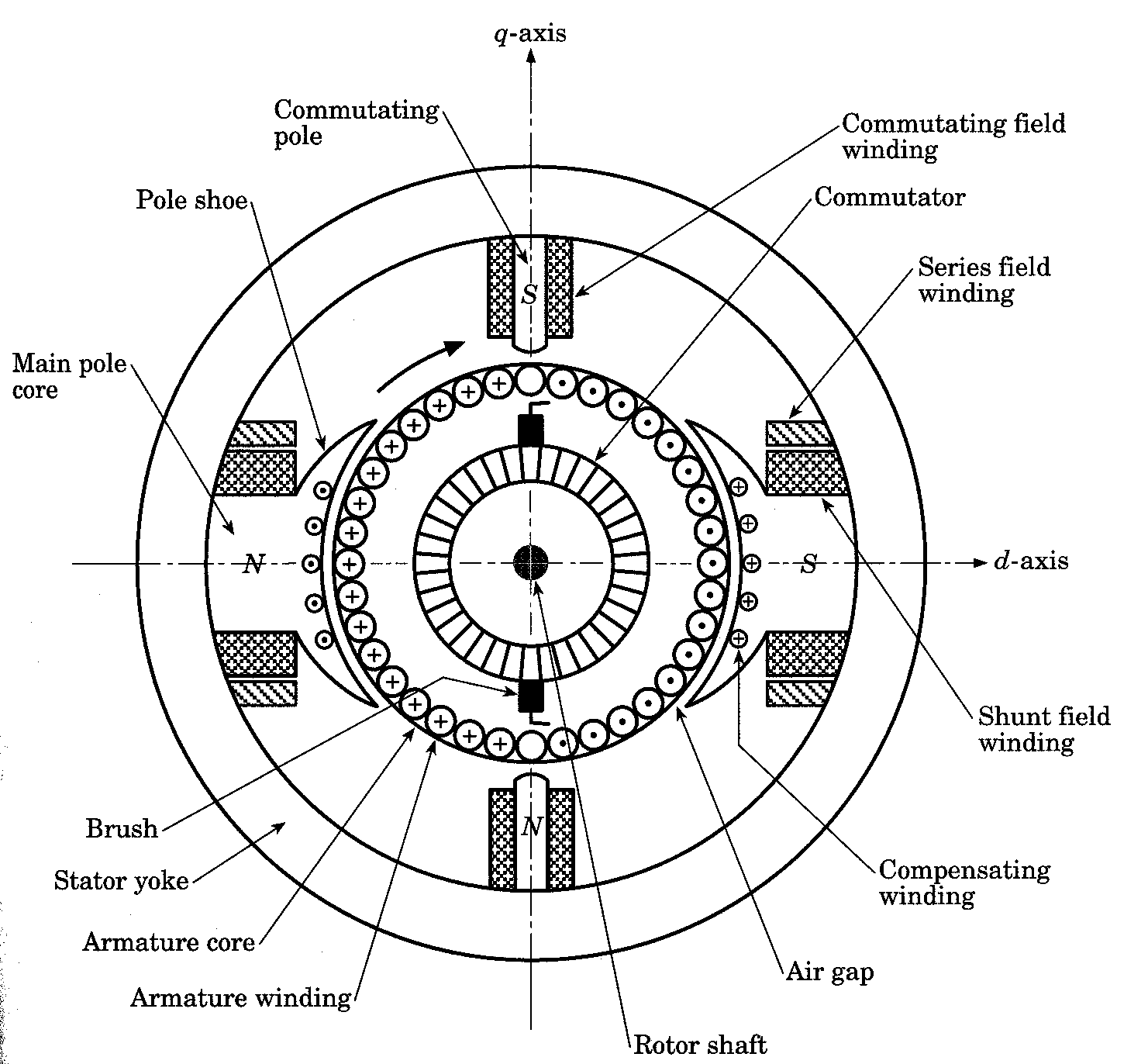
The essential parts of a DC machine are:

  1. Frame or Yoke

  2. Pole and pole shoe

  3. Field coils

  4. Armature core

  5. Armature winding

  6. Commutator

  7. Brush and holders

  8. Shaft and bearings

  9. Fan or cooling system

statorYoke: made of cast iron or fabricated rolled steel or steel casting. It act as magnetic return path, holds the poles in position and provides mechanical protection

Pole and pole shoe: They are made of MS sheets or laminated soft steel sheets punched to suitable size and stacked and riveted together. Field winding is placed on the poles. The pole shoe serves the purpose of spreading the magnetic field uniformly in the air gap.

Field coils: It is used to produce magnetic field. It is wound on a former and then placed on the pole. Insulated copper wires are used for winding. In the case of compound machine both series and shunt winding are done on the same pole.

Armature core: The primary function is to provide magnetic path of low reluctance. It is made of stamping of circular sheet steel discs of approximately 0.5 mm thickness. The slots are cut on the armature core. Slots may be open or semi closed.

rotorArmature winding: Winding is done through the slots on the armature core and is connected in succession to a Commutator segment. There are mainly two types of winding namely Lap winding and Wave winding.

Commutator and brush: It is a extension of armature to which the connections of armature winding is soldered. A brush touching the Commutator collects the current as it rotates. They are made of segments of copper bars arranged to from a cylinder and each segment is insulated from each other. The type of brush used depends on the speed of rotation. Normally carbon brushes are used. Other brushes used are, Graphite, Metal Carbon, etc.